ME360 - Electromechanical Design
Introduction
ME360 is the electormechanical design class at Boston University. The class consists of 2 main projects, and covers a variety of topics.
Solidworks Motion Studies
Throughtout this class, we utilize Solidworks motion studies to determine properties of systems in motion. This is done across 2 major projects, which include a trashcan with moving lid, and a study of an object moving between two set points.
4 Bar Linkage in Solidworks
Using a pre-made 4 bar linkage assembly in Solidworks, we conducted motion studies to determine forces, parts, and more on various parts of the assembly.
Motion Study Results
The maximum positive motor torque is 629 N-mm, and the maximum negative motor torque is -706 N-mm.
The maximum negative torque occurs at 0.68 seconds into the study. At this moment, the displacement angle is 75˚ past vertical up. The maximum positive torque occurs at 2.08 seconds into the study. At this moment, the displacement angle is 92.71˚ from vertical up
The maximum vertical force on bearing is 12.79 N, and the maximum vertical force on newBearing is -10.87 N (downward)
The minimum power required to run the motor at 600 rpm is 525.5 watts, however it must be able to dissipate over 1273 watts of power from the momentum of the crank and assembly.
The negative torque values demonstrate the momentum that the moving massive components of assembly gain. These include the crank itself, the extender, and the rocker. The negative torque symbolizes the motor working in the opposite direction of its rotation to maintain the same rotational rate. This can be caused by the extension, rocker, or crank being accelerated by gravity and the motor having to counteract that acceleration.
Trashcan with Moving Lid
The trashcan is designed to have trash placed in the top, which is then rotated towards the bottom in a manner that prevents any trash from falling out. The trash is then dumped into the side of the Big Belly trashcan.
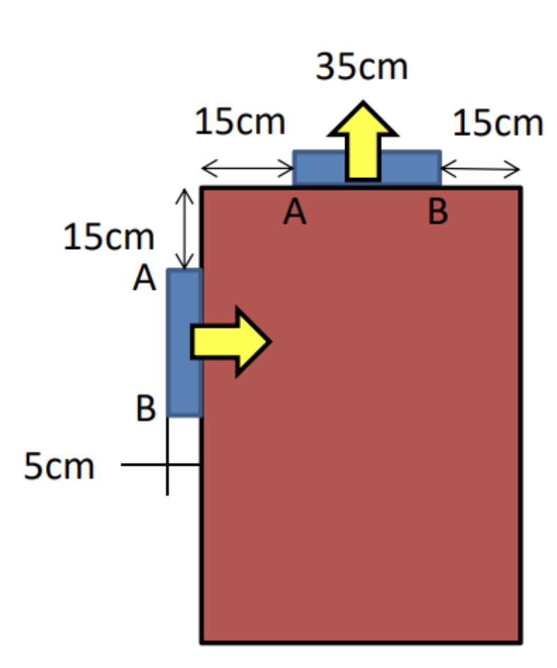
The original schematic of the trashcan we were given for this assignment is to the left. The path of motion was left entirely up to us, and the only requirement was that the trash doesn't spill out the side while the motion is happening.

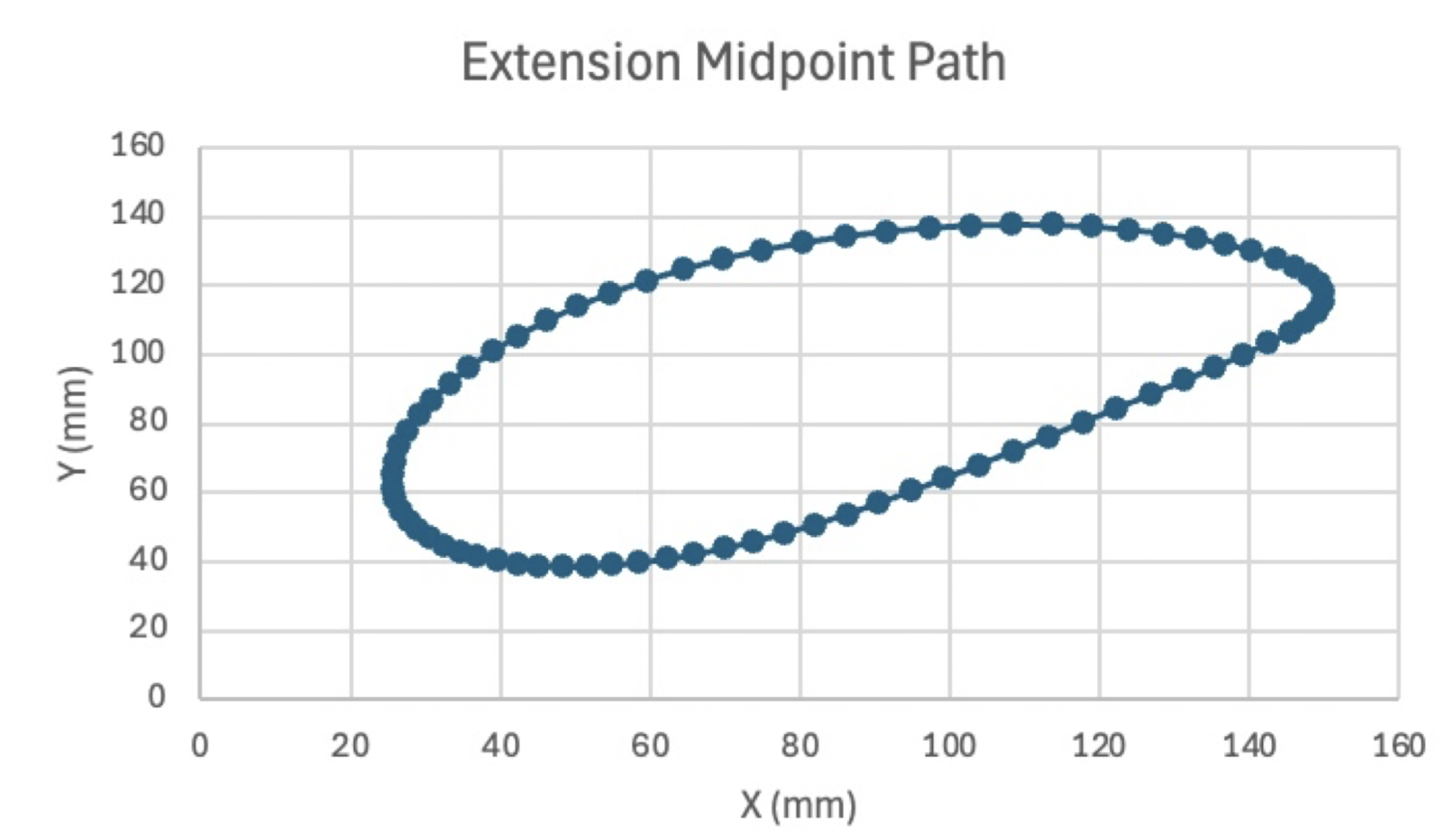
The trashcan's range of motion in a loop in Solidworks.
Motorized Cart with 80/20 as cargo
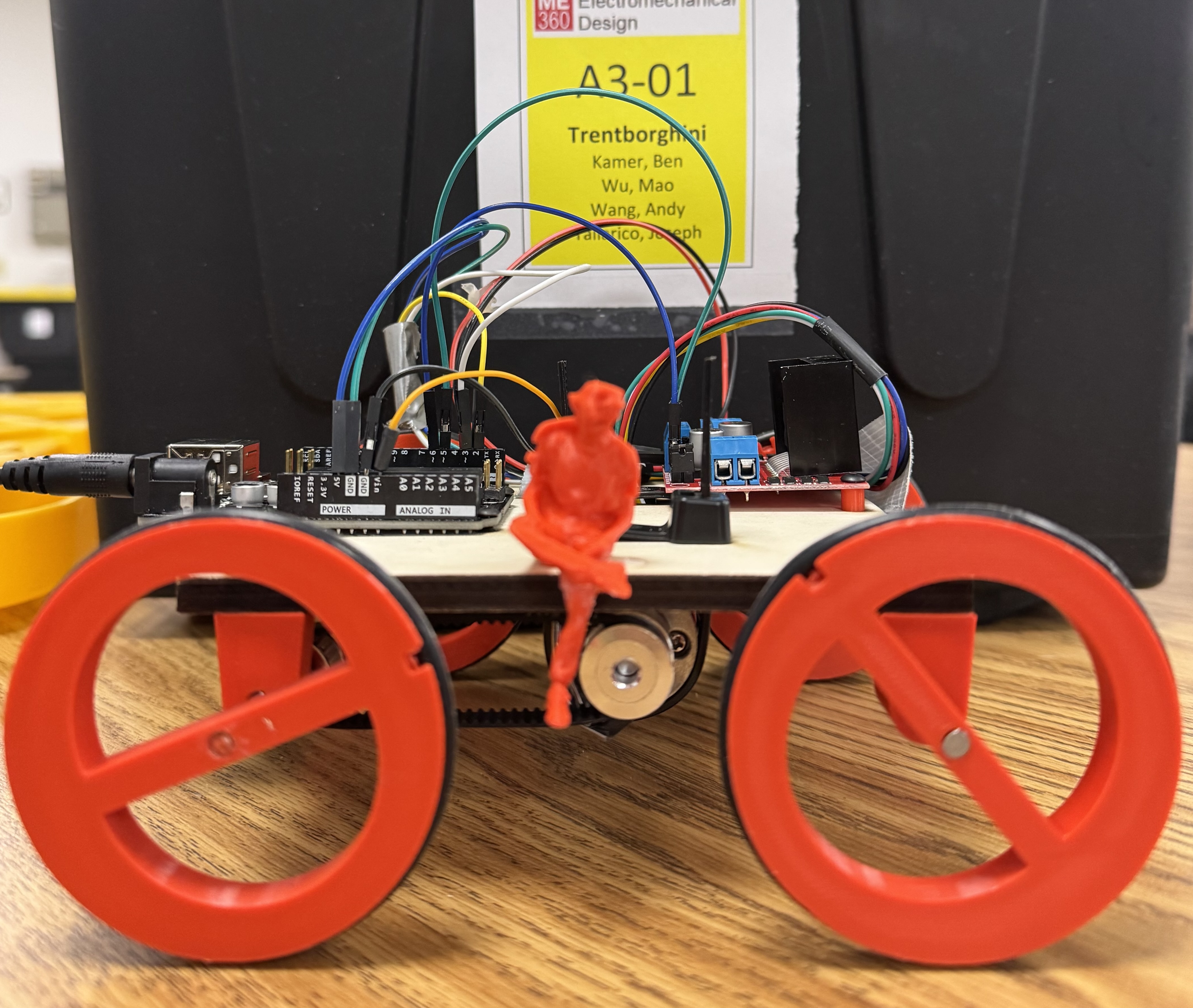
The first major project in this class was to design, build, simulate, and code a cart that is able to take a vertical 1 foot tall bar of 80/20 forward and backwards at the maximum speed possible with no added restraints.
The cart utilizes an Arduino Uno, a L298N motor driver, and a DC motor with an encoder attached. The structure of the cart was designed and lasercut, with the axle mounts and wheels being 3D printed. There is also a fun easter egg on the cart, which is a 3D scan of one of our group members, Trent, sitting on the side of the cart.
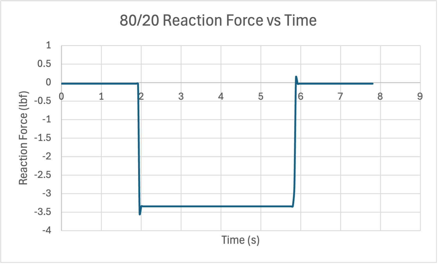
To find the max acceleration the cart could do without causing the bar to topple, a solidworks motion study was employed. The cart would move back and forth, and the resultant force on the edge of the bar would be shown. From basic mechanics, we know that the onset of tipping occurs when the normal force on the bar can no longer offset the moment caused by other forces on the 80/20. Adjusting the values within the solidworks motion study, we can also plot the acceleration of the cart, which allows us to determine the actual acceleration of our cart.
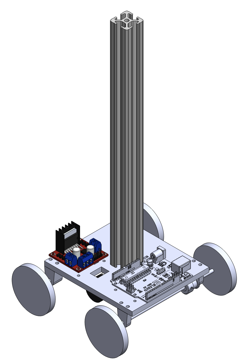
The design of the cart in Solidworks
The cart without 80/20
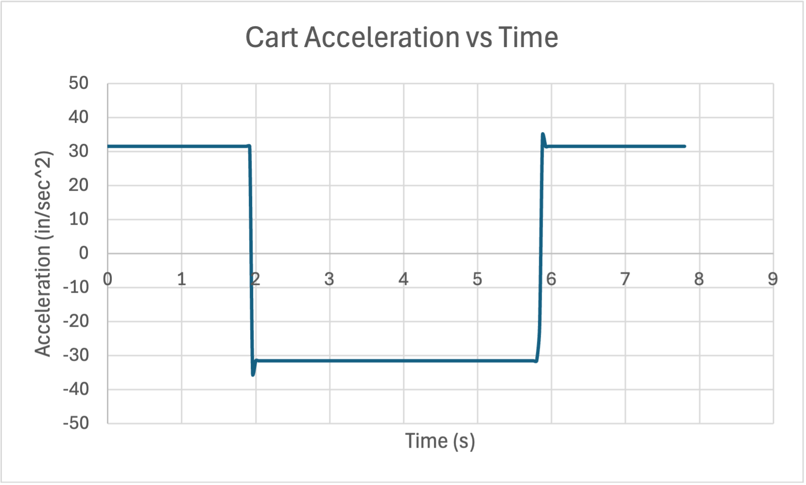
With the resulting acceleration values, we created code that utilized a proportional response to ensure that the acceleration was always closesly folllowing the simulation value. The initial revision of the code worked quite well, except that it would overshoot the distance we told the cart to travel. After adjusting some tuning values in the code and updating the way the cart counted the distance it traveled, we were able to have the cart travel both 10 feet and 5 feet accurately and quickly.
The cart in motion
2.5 DOF System
The final project in this class was to design, build, and program a 2.5 degree of freedom system. The rest of the project was up to our group's discretion. We decided to build a zen sand board, which moved a metal ball around a flat layer of sand in order to draw designs.
The sand board utilizes a Makerbase MKS Base control board to drive 3 stepper motors, 2 of which are used to move the X axis, and one of which drives the Y axis. Additionally, an end effector which holds a magnet is raised and lowered utilizing a small high torque servo motor. This allows for completely independant drawing, where the ball is returned to a home position after each drawing complete, and is picked up shortly before each drawing.
The sandboard utilizes PrusaSlicer and Repetier Host to print designs. It starts by running a custom gcode which retrieves the ball, and ensures that the end effector does not crash into the sand box supports, then after running the design, runs an additional custom gcode which returns the ball to its designated parking spot, then homes and places the end effector in a safe state and location. Because of the use of PrusaSlicer, the sandboard is able to draw almost any shape as long as it is able to be stored as a 3D or 2D geometry file, such as a STL or SVG.
The sand board drawing a spiral
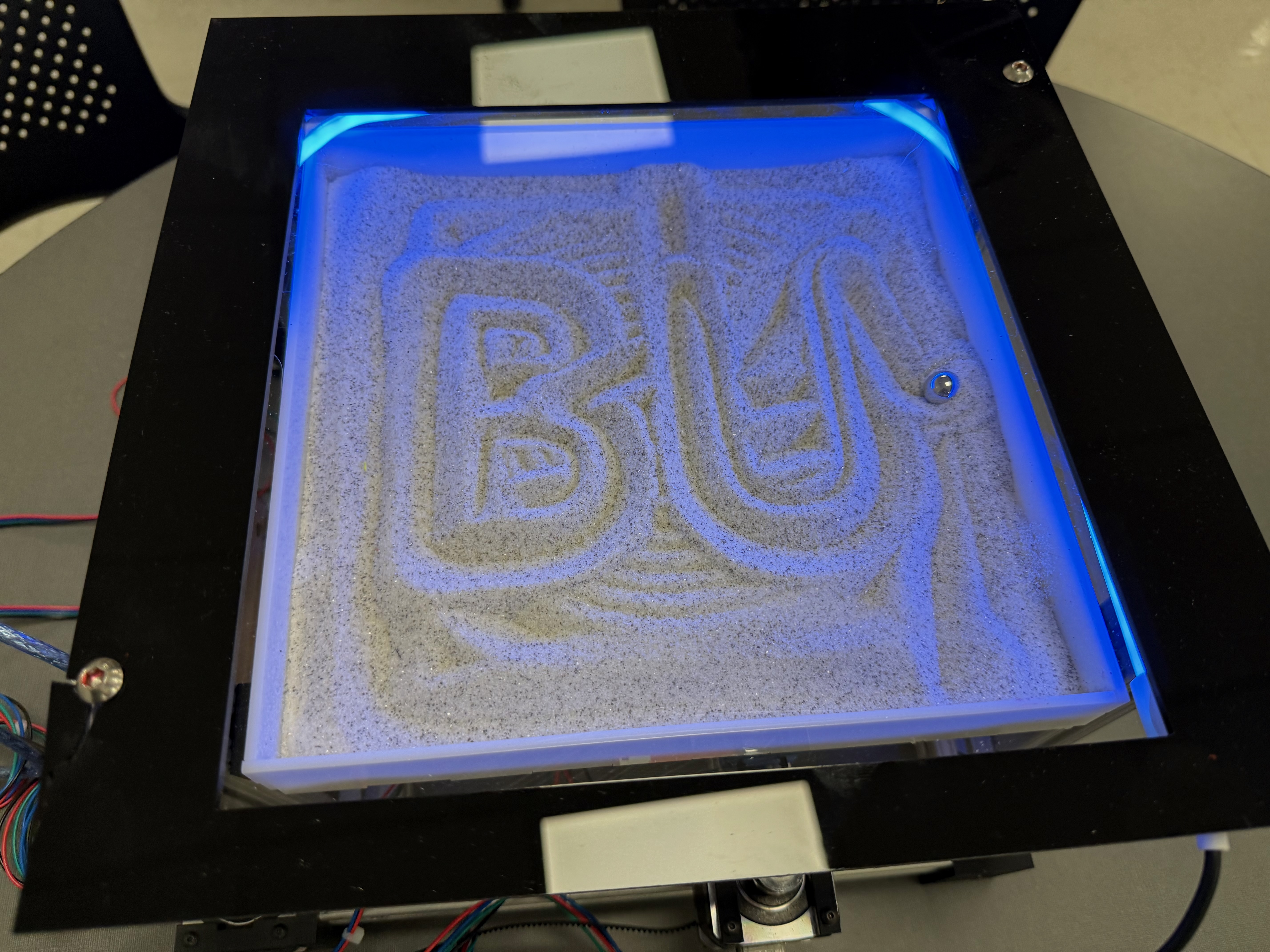
The sand board with BU drawn
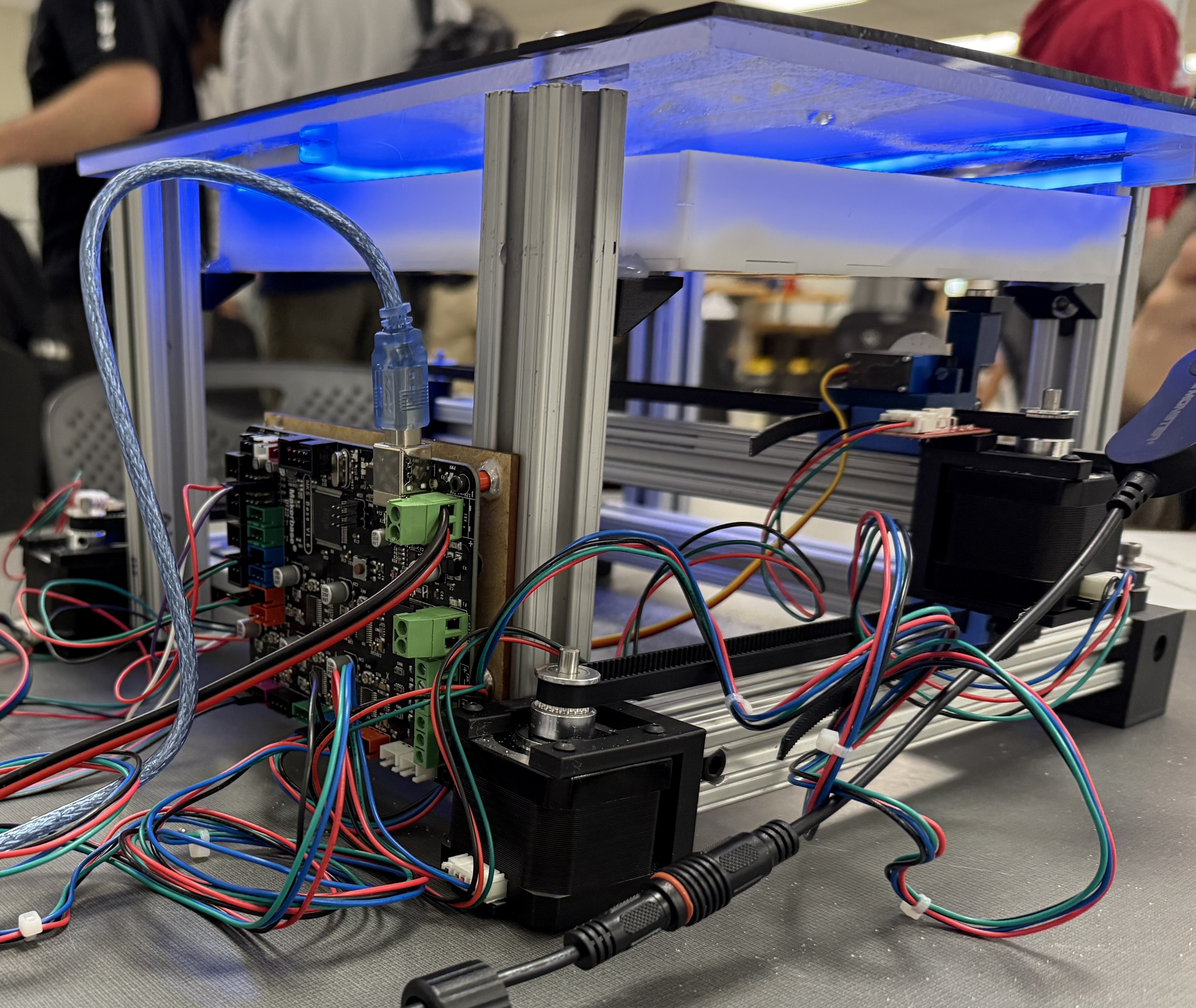
The sand board from the side